I had to get two new tyres for the Citroen while we were over Portsmouth way, so managed to find a garage just on Hayling Island that would do it on a Saturday afternoon at short notice. So while they were doing it, I took a walk. This signal is almost all that is left from the days when there was a rail link to the island.
We had some snow during Wednesday 18th, this is what it looked like: By the time the minor snow fall was over it was looking like this: I went to collect my daughter in the Land Rover and wound up driving other people to more inaccessible places also, which was great fun. This morning the snow has not melted.
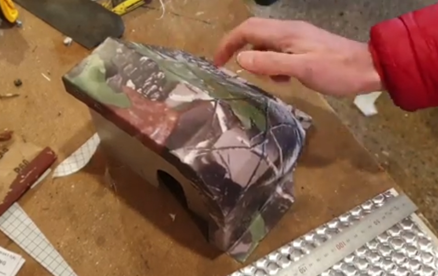
I have installed yet more Dodo matting to the dash, this time it’s the wiper motor box bit.
I put some more of the Dodo mat into the Land Rover last night. I have stuck it to the inside of the dash panels and over most surfaces which I thought might drum or rattle due to vibration. For the first time I remembered to get a video for some audio of the before and after effect of adding this stuff.
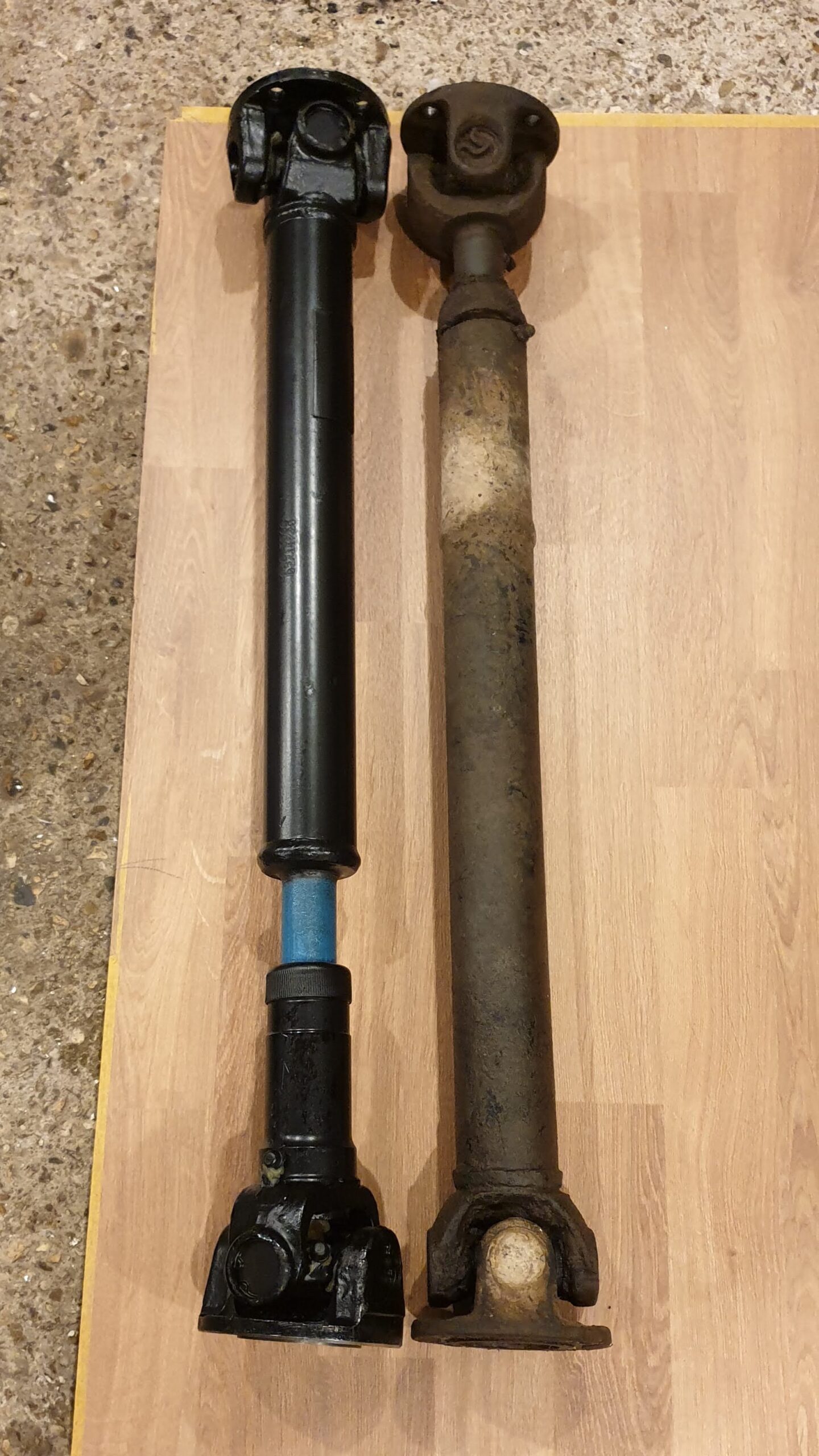
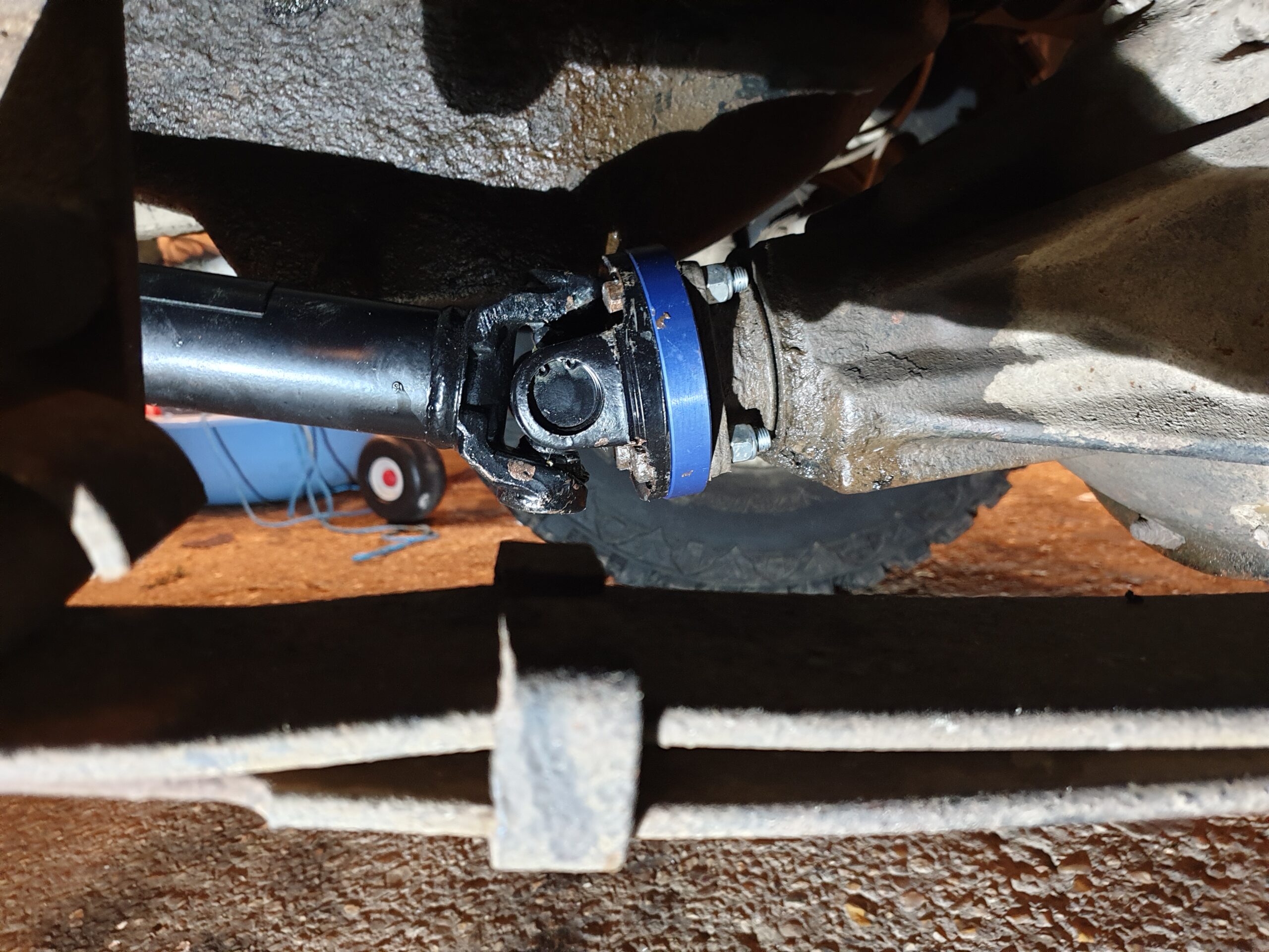
Well.. this is interesting. So the new prop came with a phase alignment of 30° out of phase. I was aware that any misalignment of of the yoke would cause vibration. But the bring diff nose points down, by perhaps 15°, so this misalignment I imagine caters for that and cancels out perhaps. Also, the splined end of the shaft has to go at one end, now I did a little googling and no one could agree on which end. Haynes manual says splines always go to the forward most end, but many say that splines should point to the transfer case. Who knows, I put with splines to the transfer case. I may well flip the front prop as I think that the other way will allow water to leave the splined end. The old propshaft was incorrectly phased for a front propshaft.
My new prop turned up today. Along with a 15mm spacer. I discovered that the prop should be 45° out of phase to remove some slop or slap or whag ever. Alan told me this, I think i need to fix the rear prop now, as i think that’s wrong also. All fitted up it is 24mm opened up. I imagine this is okay. I can’t imagine that it’s going to close up more than that and should now have some added space to open up.
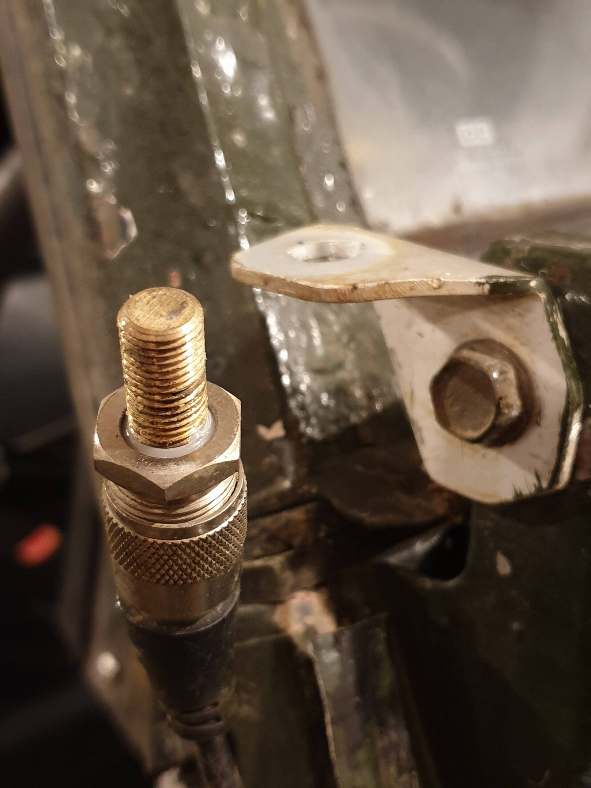
I have started sticking in the sound insulation now. I also visited a CB Radio place, which shares it’s premises with a PC repair place. The CB guy was not in, but the PC man was very helpful and suggested how I might fix my poor CB radio range. Turns out that I had isolated the aerial too well from the body work. He explained that the negative of the aerial should be bonded to the body of the Land Rover as the body acts as one half of the antenna. The silver part in the image above is the negative and is now electrically connected to the bracket and body, where as the copper centre part is the positive is isolated from the body. I have not yet tested this configuration, but I have my fingers crossed.


Recent Comments